Parameters and expressions
A design that has wall = 2.4 mm in one place and the number 2.4 typed in five others is hard
to change. Extrudo lets you name a value once and use the name everywhere, so changing it changes
everything that depends on it.
Every number is an expression
Any field that takes a number takes an expression: a number with a unit, a parameter's name, or a calculation. All of these work in a length field:
20
20 mm
wall * 1.5 + 2 mm
(width - 2 * wall) / 3
max(wall, 1.2 mm)
Under the field the app shows what the expression comes to, for example = 75.20 mm. If it
doesn't make sense, the field shows a red underline and says why, pointing at the part that is
wrong. The value isn't used until it works.
This holds in feature dialogs, in a sketch's dimension labels, in the heads-up box while you draw and in the Parameters dialog.
Units
The units are mm, cm, m, in and ft for lengths and deg and rad for angles. Write
the unit after the number, with or without a space: 10 mm, 2.5in, 45 deg.
A plain number takes the unit of the field it is in. In a length field 20 means 20 in the
design's unit (millimetres, unless you changed it), and in an angle field 45 means 45
degrees. Next to a length, a plain number joins in too: width + 2 adds 2 mm. This is what makes
quick typing work.
Beyond that, units have to add up. You can't add a length and an angle, and a parameter that is
just a number won't pass for a length: the app says "Multiply by a unit, like … * 1 mm".
There is no hidden multiplication either, so write 2 * width, not 2 width.
Operators and functions
+, -, *, / and ^ (power), brackets, and pi. The functions are:
sin cos tan |
Take an angle. A plain number counts as degrees. |
asin acos atan |
Give an angle back. |
sqrt abs |
|
min max |
Take any number of values of the same kind. |
round floor ceil |
Round in display units: a length to a whole millimetre, an angle to a whole degree. |
The Parameters dialog
Open it from Home › Parameters (it is also in the Sketch tab, since dimensions use
parameters), or search for it with Ctrl+K.
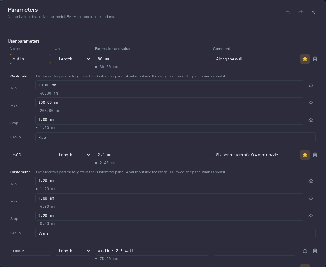
User parameters are yours. To add one, fill in the row at the bottom: a name, a Unit
(Length, Angle or Number), an expression and, if you like, a comment, then press
Add. Names can't be a unit, a function or pi. Parameters can use each other:
inner = width - 2 * wall. If they end up depending on themselves, Extrudo refuses and shows
the loop: "wall refers to itself: wall → lid_gap → wall."
Model parameters are the values in the design that already have names, listed under the
feature they belong to. A dimension you placed in a sketch is d1, d2 and so on, and so are
the values in feature dialogs. You can edit them here, and use them in other expressions. Rename
a dimension by typing name = value in its editor, as described in
sketching.
Changing a parameter is one undo step, however many sketches and features it moves. Deleting one that something uses is refused, and the message lists what uses it.
The Customizer
The Customizer is a panel of sliders for the few parameters someone changing your design would reach for, and none of the rest. It is how a design becomes a small configurable product.
To put a parameter there, click its star in the Parameters dialog. Under the row you can set a Min, a Max, a Step and a Group. A parameter with a range and a plain value gets a slider. Parameters with the same group are shown together, such as Size and Walls. The ranges are only the slider's range: you can type a value outside it, and the panel warns that it is outside.
Open the panel from Home › Customizer. Dragging a slider moves the model live, and the whole drag is one undo step.
Configurations are saved sets of values. The panel's Configuration menu lists them, and choosing one sets every exposed parameter at once. Under the ⋮ menu are Save as… (a new configuration from the current values), Update, Rename… and Delete. There is no "active" configuration stored in the design: the panel shows the one whose values the design has right now, and Custom when none matches. The templates on the home screen come with some, such as Small and Large for the Storage box.
Print tolerance
Printers don't make parts to the exact size you draw. A hole prints a little small and a peg a
little large, so a part that has to fit another needs a clearance. Extrudo has one parameter for
it, named tolerance.
Set it in 3D Print › Prepare › Tolerance: type a value, or press Tight (0.1 mm),
Normal (0.2 mm) or Loose (0.3 mm). The panel counts how many places use it. It is an
ordinary parameter, so you can also use tolerance in your own expressions.
Two features follow it by themselves:
- Hole presets for clearance holes and heat-set inserts add the tolerance
to every diameter they fill in. With the parameter set, the M3 clearance preset writes
3.4 mm + 2 * tolerance. - Thread cuts its profile in by the tolerance, so a thread you cut on a
bolt and one you cut in a nut meet with a gap. The dialog proposes the
toleranceparameter when the design has one.
Without a tolerance parameter the presets write plain numbers and a thread uses 0.1 mm.
Change the value later and every hole and thread that follows it changes with it.